Expanding on W1GHZ GaAsFET LNA Bias with Optocouplers
After reading the W1GHZ GaAsFET LNA Bias entry, I wanted to see what the performance of these exposed-base optocouplers are. The concept comes from the IEEE Microwave Journal Application Notes: Photovoltaic Bias for Depletion-Mode Devices in Low-Noise Amplifier Applications (DOI 10.1109/MMM.2022.3226635). It's not open access, so I figured some publicly available characterization data would be cool to share. I have access to a dual-channel precision SMU (source-measure unit, Wikipedia) and that's exactly what we need to characterize the photovoltaic behavior of optocouplers!
 |
| Keysight B2902B SMU front panel during a 20 mA input, open circuit output measurement |
First up is the exposed-base optocoupler operating in photovoltaic mode; essentially it's a tiny solar panel inside. Paul suggests the Vishay 4N25 series while I tried the slightly cheaper on Digikey CNY17.
 |
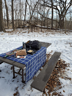
| Measurement setup for the CNY17 (alongside the MOC3023 to be mentioned later) |
The CNY17 I had was a SMD version and the Digikey sourcing information stated a date code of 2216 and lot code of 221140060. Channel 1 is the output side with kelvin clip 4-wire measurement and channel 2 is the LED input drive just as a 2-wire measurement. First up is the open circuit test:
| CH 2: LED | CH 1: Photo Output | ||
|---|---|---|---|
| Iset | Vmeasure | Iset = 0 | Vmeasure |
| 100u | 0.97978 | open circuit | -0.32 |
| 1.0000m | 1.08090 | 0.44290 | |
| 5.0000m | 1.15001 | 0.50092 | |
| 10.0000m | 1.1848 | 0.52330 | |
| 20.000m | 1.2284 | 0.54462 | |
Then is the short circuit test:
| CH 2: LED | CH 1: Photo Output | ||
|---|---|---|---|
| Iset | Vmeasure | Vset = 0 | Imeasure |
| 100u | 0.97916 | short circuit | -0.03u |
| 1.0000m | 1.08075 | -1.436u | |
| 5.0000m | 1.14996 | -12.488u | |
| 10.0000m | 1.18485 | -27.667u | |
| 20.000m | 1.2282 | -57.25u | |
These are non-pulsed measurements since the heating effects are mostly marginal, the DC conditions are mostly what we care about in this application, and I didn't care to figure out what settings I would need for reasonable measurements with this instrument.
I followed this up by slapping a load resistor on the output, choosing a 30.9k 1% 0603 thick film from the convenient surplus resistors to approximately match Paul's 10k potentiometer in series with 15k recommended. circuit. Giving it a full 20.000 mA LED drive setpoint on the ~23°C lab bench, I got:
| CH 2: LED | CH 1: Photo Output | ||
|---|---|---|---|
| Iset = 20 mA | Vmeasure | Iset = 0 | Vmeasure |
| Initial | 1.2208 | open circuit | 0.5163 |
| 30 minutes | 1.2276 | 0.52807 | |
| Next day | 1.2277 | 0.5283 | |
Thus, loading down the output in the 10s of kOhm range is a perfectly reasonable thing. Note that the meter itself is acting as an open source, but the added output load resistor is there to sink a couple microamps.
Since there was one sitting around the lab, I tried an opto-triac, MOC3023, and it doesn't produce useful photovoltaic output. There's some output voltage produced, but the short circuit current at the exposed substrate (MT1 and MT2 shorted) ends up being 2.3 nanoamps with 20 mA LED input current. I don't think PVC wires are good for measuring at that level!
One of the alternatives for additional output voltage is a photovoltaic FET driver that produces lots of voltage, I used the TLP3905. It's rated at 10 mA input LED current for a minimum of 7 V open circuit and 12 uA short circuit. On the bench, it'll do more than that!
 |
| Measurement setup for TLP3905 (also showing the load resistor on the CNY17) |
Open circuit test:
| CH 2: LED | CH 1: Photo Output | ||
|---|---|---|---|
| Iset | Vmeasure | Iset = 0 | Vmeasure |
| 100u | 1.3747 | open circuit | 7.6659 |
| 1.0000m | 1.4611 | 9.3352 | |
| 5.0000m | 1.5506 | 10.4314 | |
| 10.0000m | 1.6145 | 10.8643 | |
| 20.000m | 1.7103 | 11.262 | |
Then the short circuit test:
| CH 2: LED | CH 1: Photo Output | ||
|---|---|---|---|
| Iset | Vmeasure | Vset = 0 | Imeasure |
| 100u | 1.3744 | short circuit | -0.147u |
| 1.0000m | 1.4610 | -2.571u | |
| 5.0000m | 1.5504 | -15.028u | |
| 10.0000m | 1.6144 | -30.992u | |
| 20.000m | 1.7104 | -62.515u | |
Interestingly, the short circuit currents are rather similar to that of the exposed-base transistor output device. Quite obviously there are many more junctions contributing to the output voltage. Assuming similar silicon junctions, this is almost exactly 20x the transistor! Of course, that's far more than these high-performance RF FETs need for bias in comparison to driving power devices rated at 4.5 to 10 V for full enhancement in a solid-state relay application. One disadvantage to some of these devices is they have a smart turn-off circuit, so it's best to look for one that is just a photodiode stack like this one to avoid funny transients when you power down the LNA.
An alternative to the suggestion to use two optocouplers for additional open circuit voltage is a linearized dual-photodiode optocoupler: has specified photovoltaic parameters, but they're expensive. Almost as expensive as Paul's whole assembled board! But it would save space in 1x 8-pin DIP versus 2x 6-pin DIP. Consider the IL300, rated at 10 mA input LED current for typical 500 mV open circuit and 90 uA short circuit for each detector. Pop the pair of detectors in series for a full volt of negative bias with no safety isolation. If there's interest, I can see about getting one and characterizing it.
If there are any other devices with integrated photovoltaic capability and functional (or better) isolation that you think I should consider, please let me know!
Or challenge yourself and the RF stability with a grounded gate and series resistors on the FET source like the SKY65050-372LF recommends (a FET that hits pinch-off at -0.95 to -0.65 V, so one of the cases for the photovoltaic driver or linearized dual-photodiode optocouplers).
Comments
Post a Comment