Last left off in the preview "teardown" despairing over the potting was my failed MEAN WELL HLG-320H. Then came a great need for mindless stimulation after a day of work and I tried cracking the case again. After the successful prying came picking and cutting away at the potting material to see what's what. Here's what's inside!
Image warning: there's a lot to get through this whole device. Click on the photo for the full Blogger resolution.
 |
There you go, just a bit more force and the top plate comes off.
|
Once actually inside the case comes the matter of detaching the brick of material from the lower enclosure and then digging into the potting material. It's a rubbery, fragmenting substance except for the very elastic stuff used to seal the end caps before the big pour.
 |
IP rating demands gasketed screws to hold the internal heatsinks against the wall of the case. Saw this style previously on a distributor site, and now in an actual application!
|
 |
Cutting out three corners of potting reveals the screws holding the board assembly to the bottom of the case allowing the brick of the board to be pulled out.
|
 |
Looking at the plastic insulation layer and uh-oh, that looks like magic soot.
|
 |
A closer look at the insulation tape and something definitely let out the magic smoke.
|
 |
Anyways, time to chip away at the potting to see what's inside.
| |
 |
Nice big air pocket: your reminder that potting doesn't totally encapsulate or insulate without special processes.
|
 |
Little air bubbles along the edge of the board on the secondary side.
|
 |
A smattering of tiny air bubbles trapped against the board next to the transformer blade-style pins.
|
 |
Magic soot on the middle of the three heatsinks. Each heatsink with associated plastic nut holders that correspond to the gasketed screws on the outside of the case.
|
 |
Solder side mostly picked free of potting except under the shield board soldered over the primary side switching controllers.
|
 |
Primary side AC input with the filter common mode chokes and PFC inductor partially exposed.
|
 |
While using a bamboo skewer for chipping potting material is a low hazard to the components on the board, this low-voltage, primary-side electrolytic capacitor still got stabbed and its vent ruptured.
|
 |
Under the main transformer and on the secondary side near the voltage/current limit potentiometers are the silkscreen text identifying the board as HLG-320HA-R10 2014/06/10 PCB:HLG-320B
|
 |
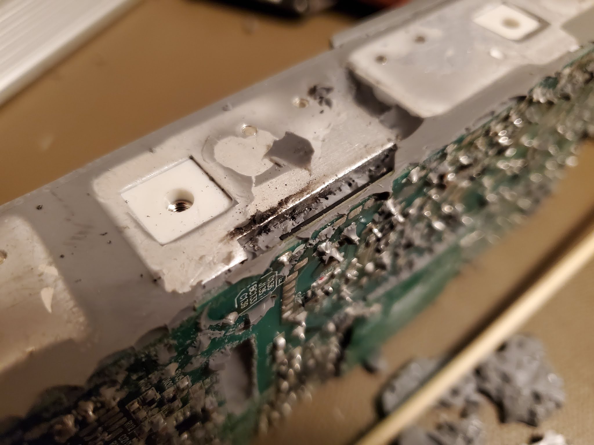
Completely chipping away the potting was a pain, as was desoldering the support pin for the heatsink, but here's our point of failure.
|
 |
Exit of magic smoke left craters in the transistors.
|
 |
The half-bridge switches are labeled 26NM60N with date code 349 (2013 week 49?). Note the different staggering of the insulated TO-220 pins between the two devices.
|
Device: ST Micro STF26NM60N
 |
Cleaned up the thermal paste and the high-side FET is absolutely cratered. That'll definitely eliminate getting any output.
|
 |
Taking a look around back: the PFC controller NCP1605G (right) and PWM controller L6599ATD (left). These are shielded by the square of PCB seen earlier.
|
Devices: ON Semi NCP1605 and ST Micro L6599AT.
 |
And over to the secondary side there's the synchronous rectifier controllers EA1791A (upper, 2x) and op-amp 258A (lower).
|
Devices: NXP TEA1791AT and ST Micro LM258.
 |
Overview of solder side of the board with better lighting and the primary side controller shield removed.
|
 |
Overview of the component side of the board with the remaining potting from the excavation and half-bridge heat sink removed.
|
 |
The simple tools of attack. A bamboo skewer really is the tool to use for limiting damage to components when excavating this type of potting compound.
|
And that's the rundown. I'll go through additional effort to see what else there is to discover on the board in the future. In particular, identifying the other major semiconductor devices used in the design. At the very least, it looks like the PFC boost FETs are the same STF26NM60N as the primary half-bridge.


Nice teardown...I have a question about potting, do you know which kind of potting is this,
ReplyDeletePolyurethane or something else? Thanks in advance.
I'm not too familiar with identifying potting compounds, but it does look like polyurethane. Taking a quick look at the options, this definitely isn't an epoxy or silicone, so that indicates a likely material.
Delete