Building a Moxon for 223 MHz
With an Elk Antennas 2M/440L5 providing me directional operation on 2m and 70cm and a couple handheld rigs that include 1.25m, I wanted more than just a stock whip to operate with those rigs. Since I have access to scraps of copper refrigerant tubing at the day job from test/prototype systems, I thought it'd be a great material to build with. To put it briefly, the results have been fantastic to start.
 |
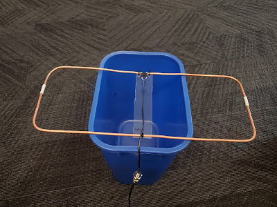
| As initially assembled on the terribly scientific test stand of an empty recycle bin. |
The design uses the W4/VP9KF Moxon Calculator with the inputs 223 MHz and 4 mm. I sketched out the key dimensions on a piece of scrap cardboard (taking two or three tries to get my use of the tape measure right) to act as a template for the tube lengths. All three pieces of scrap originally had 90° bends included, so only one reflector corner had to be hand-bent.
The end spacers between the two elements are scrap refrigerator water line pieces. Quite easy to cut, but took some development of technique to get the copper to fit inside stably. Future attempts will require deburring the outside of the cut copper followed by expanding the end of the plastic with a different sized pen tip. The plastic water line relaxes after the deformation and holds the copper fairly snugly. While not strong, the assembly was self-supporting before the addition of the central support.
For that additional support, a conveniently sized slice of polycarbonate with holes for zip ties fits the bill. With the hole placement, it's probably slightly too short, but keeping the element spacers under compression is advantageous. This also provided a convenient place to label the elements and mark the radiation direction for clarity.
The feedpoint is actually modular and is composed of 4 populated positions of 7 from a 0.1" pitch pin header. On the cable is two positions of 5 on a 0.1" pitch socket header. This provides some mechanical stability to the driven element feedpoint spacing and allows me to change out the cable (upcoming work). There's also the option of placing a balun here, but it seems that usually isn't critical for VHF, especially at QRP.
 |
| Uncalibrated NanoVNA reading from the antenna in the test position. Tuned right in per the design! |
My first try to get the NanoVNA hooked up was thwarted by failing to solder well-aged RG-174 braid to the 0.1" pitch socket pin, requiring a reset to my final assembly process. Some trimming and flux later, I was able to get it connected correctly and then the antenna on to test. Center = 225 MHz and Span = 50 MHz, trim down the visible traces, and set the marker search to Minimum: boom, whatever errors may have accumulated in the measurement, cutting, and assembly process worked out.
Now, I don't have an antenna test range or really any great way to test this build, but I will be putting it to use and seeing if I can manage some new VHF FM DX of sorts in the future.


Comments
Post a Comment